globalgrid2050
Grid Scale Battery Energy Storage Systems
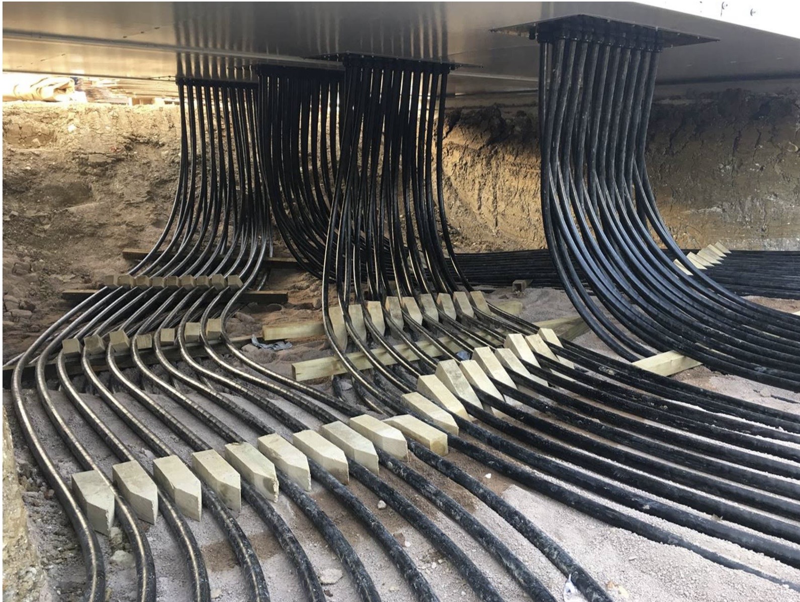
Project reference: Pelham Battery Energy Storage System - PCS to BESS
Typical PCS to BESS cable interface illustrating parallel cable routing, grouping and installation constraints
Installation: Sphere Electrical
Cable engineering support: VENTUS Ltd
Table of Contents
- The Baseline Requirement
- Scope Context
- Purpose
- Commercial Risk Position
- System Overview and Behaviour
- Standards, Definitions and Conventions
- Engineering Definition Framework
- Engineering Scope Breakdown
- Engineering Outputs
- Total Engineering Effort
- Compliance Position
- Engineering Reality
- Recommended Engagement Approach
- Professional Validation Requirement
- Disclaimer
The Baseline Requirement
Utility scale battery systems routinely start construction with incomplete electrical definition. This creates latent failure risk across cable systems, protection and system behaviour.
This page defines the minimum engineering scope required to move from concept to a bankable, safe and operable system.
Scope Context
This example focuses on the cable interface between the Power Conversion System and the Battery Energy Storage System.
Refer to the Pelham Battery Energy Storage System project video for installation context.
Pelham represents an early generation 1 hour duration system and is used here as a reference for electrical architecture rather than modern storage duration.
The sections below define the minimum engineering scope required to achieve:
- compliant Single Line Diagrams
- validated power system studies
- bankable electrical design
for utility scale battery storage systems.
Purpose
To define the engineering scope required to move from concept design to verified electrical system, ensuring:
- compliance with BS 7671 and applicable IEC standards
- correct protection and fault behaviour
- thermally and electrically valid cable systems
- long term reliability and safety
Commercial Risk Position
Failure to execute the engineering scope defined below routinely results in severe project impacts:
- Delayed energisation due to failed protection coordination or grid compliance.
- Cable system overheating and premature failure.
- Inverter/PCS instability due to unverified system interaction and harmonics.
- Rework of installed infrastructure during the commissioning phase.
- Loss of lender confidence and delayed financial close.
- Transformer failures - unexpected system behaviours, harmonics, waveform distortion, moisture ingress etc frequently causes transformer strain or catastrophic failure in the worst case
These risks originate from incomplete engineering definition, not construction error.
System Overview and Behaviour
A grid connected utility scale battery energy storage system requires precise definition of both physical architecture and dynamic electrical behaviour.
System Architecture and Interfaces
- Block architecture: Containerised vs centralised Power Conversion Systems (PCS) and transformer units.
- Electrical interfaces: Clear demarcation at the grid connection point, PCS to transformer (LV/MV), PCS to battery (DC) and auxiliary LV supplies.
- Redundancy and aggregation: Number of parallel circuits and aggregation methodology at the MV level.
Power Flow and Control Philosophy
- Bidirectional operation: Active and reactive power flow definition across charge and discharge cycles (AC to DC and DC to AC).
- Control mode: Grid-following versus grid-forming inverter operation, including frequency response and voltage support capability.
Fault and Transient Behaviour
- Fault current paths: Expected magnitude, duration, and routing of fault contributions from the grid, inverter (PCS) and battery systems.
- Transient response: Transformer energisation (inrush), switching transients from MV equipment, and DC-side behaviour during faults or disconnection.
- Harmonics and power quality: Expected harmonic injection from power conversion systems, interaction with grid impedance and requirement for harmonic filtering.
Cable System and Thermal Environment
- Cable behaviour: Parallel cable operation, current sharing, electromagnetic coupling between circuits and installation geometry impact on inductance. Cable system behaviour, particularly under parallel operation and thermal interaction, is one of the least understood and highest risk elements in BESS design.
- Thermal environment: Precise definition of installation conditions (buried, ducted, air), factoring in ambient temperature assumptions and the impact of grouping and load diversity.
- Failure considerations: Loss of PCS block, cable failure and isolation strategy, protection misoperation scenarios, and thermal overload conditions.
Standards, Definitions and Conventions
Purpose
To ensure consistency, traceability and compliance across all engineering outputs including Single Line Diagrams, calculations and specifications. All documentation shall align with recognised UK, IEC and international standards.
1. Electrical Design Standards
- BS 7671: Requirements for Electrical Installations. Governs electrical safety, protection, earthing, cable selection and verification.
- IEC 60364 series: International basis for low voltage electrical installations and system design principles.
2. Battery Energy Storage System Standards
There is no single UK BESS design standard, therefore multiple standards apply:
- IEC 62933 series: Electrical energy storage systems, system level requirements and performance.
- IEC 62619: Safety requirements for lithium ion battery cells and systems.
- IEC 63056: Safety requirements for secondary lithium cells in energy storage applications.
- IEC 62477 series: Safety requirements for power electronic converter systems.
- BS EN 50549: Requirements for generation connected to distribution networks.
- ENA G99 / G100: UK grid connection, protection and export limitation requirements.
3. Power System Study Standards
- IEC 60909: Short circuit calculation methodology (UK and Europe).
- ANSI C37 series: Alternative short circuit methods (US based, only where specified).
- IEC 61000 series: Electromagnetic compatibility and harmonic limits.
4. Cable Design and Thermal Standards
- BS 7671 Chapter 52: Cable selection and installation.
- IEC 60287: Cable current rating and thermal calculation.
- **FEA - Finite Elements Analysis models to account current and voltage changes as the system is not steady state. This requires MATLABs or equivalent models. The risk to avoid is transformer and PCS failure with intermittent loading!
5. Earthing and Safety Standards
- BS 7671 Chapter 41 and 54: Protection against electric shock and earthing systems.
- ENA TS 41-24 / IEEE 80: Substation earthing and step and touch voltage design (where applicable).
6. Drawing Standards (SLD Format and Structure)
The following standards define how electrical diagrams shall be produced:
- BS EN 61082: Preparation of electrotechnical documentation and drawings.
- BS EN 60617: Graphical symbols for electrical diagrams.
- IEC 81346: Reference designations and system structuring.
SLD Requirements: All Single Line Diagrams shall:
- Clearly define system topology and hierarchy.
- Identify all sources, loads and interfaces.
- Show protection devices and ratings.
- Indicate earthing arrangement.
- Be consistent with calculation models and studies.
7. Naming, Tagging and Nomenclature
- Equipment tagging shall follow IEC 81346 principles.
- Consistent naming across SLDs, layouts, studies, and asset registers.
- All identifiers must be unique, traceable, and consistent across all documentation.
8. Units and Measurement Conventions
All engineering values shall use SI units. Key conventions:
- Power: W, kW, MW
- Energy: Wh, kWh, MWh
- Voltage: V, kV
- Current: A
- Frequency: Hz
- Temperature: °C
- Time-based performance (e.g. storage duration) shall be clearly defined (Example: 50 MW / 50 MWh = 1 hour duration).
9. Documentation Consistency Requirement
All outputs must be aligned with the above standards, internally consistent across drawings and studies, traceable to assumptions and calculations, and suitable for independent engineering verification.
The Bottom Line: Drawings, calculations and specifications must form a coherent, traceable system definition.
Engineering Definition Framework
Indicative. Costs may vary according to negotiated scope and number of hours needed.
Engineering Basis
Engineering rate: £95 per hour
All values are indicative and depend on:
- project maturity
- data availability
- complexity of grid interface
- level of prior engineering
Governance requirements:
- Named Engineer of Record per discipline
- Independent Checking Engineer with equivalent competence
- Full traceability of all assumptions and calculations
Engineering Scope Breakdown
1. Core Electrical Definition (SLD and Grid Interface)
Competence: Senior Electrical Engineer (33 kV to 132 kV)
Hours: 120 to 250
Cost: £11,400 to £23,750
2. Power System Studies
Competence: Power Systems Engineer
Hours: 250 to 600
Cost: £23,750 to £57,000
3. Medium Voltage Cable System Definition
Competence: HV Cable Engineer
Hours: 150 to 400
Cost: £14,250 to £38,000
4. DC Cable System (Battery to PCS)
Competence: DC Systems Engineer
Hours: 100 to 250
Cost: £9,500 to £23,750
Note: Verified thermal study (IEC 60287) required for bankability (£8,000).
5. Low Voltage Distribution Design
Competence: LV Electrical Engineer
Hours: 80 to 200
Cost: £7,600 to £19,000
6. Earthing and Bonding Design
Competence: Earthing Specialist
Hours: 200 to 500
Cost: £19,000 to £47,500
7. Protection and Control Philosophy
Competence: Protection Engineer
Hours: 150 to 350
Cost: £14,250 to £33,250
8. Substation and Switchgear Definition
Competence: Substation Design Engineer
Hours: 150 to 300
Cost: £14,250 to £28,500
9. System Integration
Competence: System Integration Engineer
Hours: 100 to 200
Cost: £9,500 to £19,000
10. Civil and Cable Installation Interface
Competence: Civil Electrical Interface Engineer
Hours: 80 to 200
Cost: £7,600 to £19,000
Engineering Outputs
Execution of the scope defined above will yield the following verified deliverables:
- Fully defined Single Line Diagram aligned with all studies.
- Short circuit and load flow models.
- Cable thermal calculations with explicit installation assumptions.
- Protection coordination study and settings philosophy.
- Earthing design with step and touch voltage validation.
- System behaviour definition under fault and transient conditions.
Total Engineering Effort
Total hours: 1,380 to 3,250 Total cost: £131,100 to £308,750
Compliance Position
A compliant design requires:
- SLD reflecting full system architecture
- calculations validating protection, thermal and fault behaviour
- studies confirming real system performance
Compliance with BS 7671 and IEC standards requires validation through calculation and study, not declaration.
Engineering Reality
- An SLD without validated studies is not a design.
- Cable sizing without IEC 60287 validation is not compliant.
- Protection without coordination studies is not operable.
- Earthing without calculation is not safe.
Such systems should not proceed to procurement or construction.
Recommended Engagement Approach
To mitigate early-stage risk, we recommend a structured transition into full definition:
Phase 1: Project Baseling
- System definition workshop
- Data validation
- Initial SLD and study framework
Phase 2: Core Engineering
- Full engineering definition and execution of system studies
Phase 3: Delivery Integration
- Independent validation and construction support
Professional Validation Requirement
All engineering used for procurement or construction must be:
- produced or verified by qualified Chartered Engineers
- supported by traceable calculations
- covered by professional indemnity insurance
This level of engineering definition is required for any project seeking reliable operation, regulatory compliance and financial close.
Disclaimer
This document defines engineering principles only. Project-specific validation is required prior to design, procurement or construction.